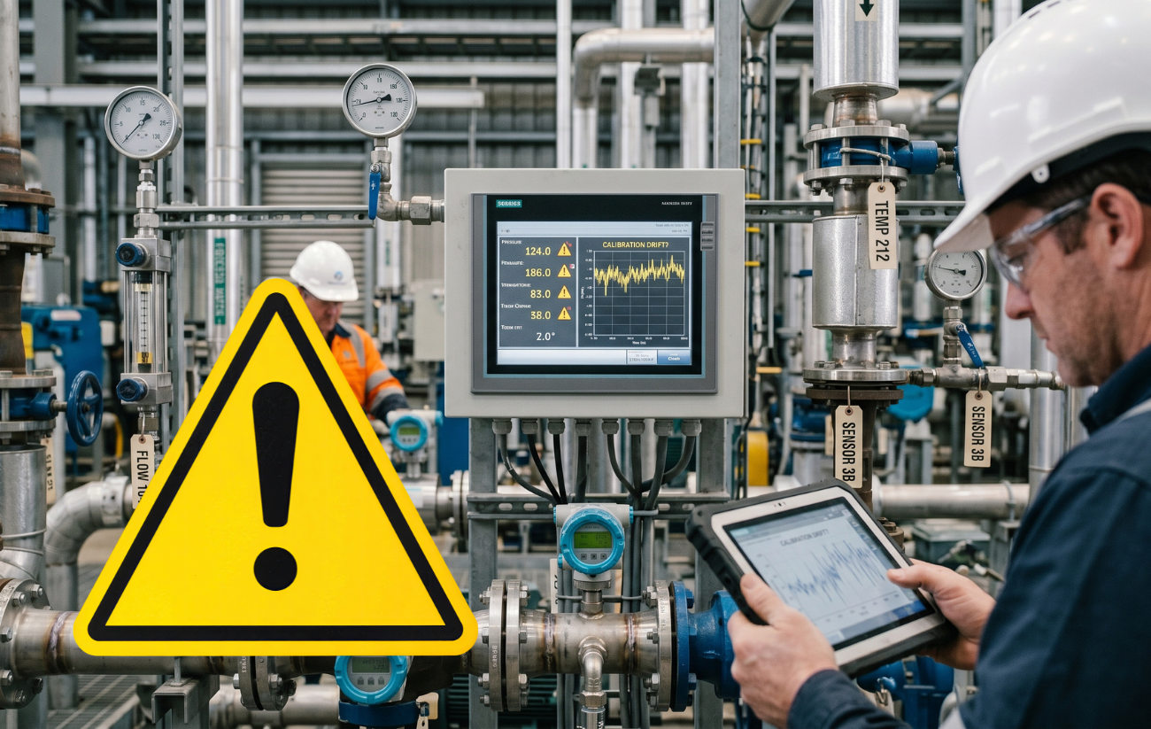
Why You Have Incorrect Measurements in Your Industrial Process – Real Causes and Practical Solutions
In industrial instrumentation, an incorrect measurement is not just a wrong number on a screen. It is a wrong decision made by a PLC, an incorrect chemical dose introduced into a reactor, unnecessarily high energy consumption or, in serious cases, a safety hazard on the production line.
Many companies invest in expensive sensors, pressure transmitters with 0.075% accuracy, and Coriolis flowmeters – and yet their processes operate with errors that significantly exceed the manufacturer’s specifications. The cause is almost never the sensor itself. The cause lies in how the instrument was selected, installed, calibrated, or maintained.
This article explains exactly why incorrect measurements occur in industrial processes and how you can eliminate each category of error.
Why Accurate Measurement Really Matters
Measurement errors have consequences that accumulate over time:
- Inconsistent product quality – in the food, pharmaceutical, or chemical industry, a 2°C error in reactor temperature can push a batch outside its specification.
- Hidden energy costs – a flowmeter that underestimates actual steam consumption by 5% can mask losses of tens of thousands of euros per year.
- Unplanned maintenance – when process data does not reflect reality, equipment failures occur without warning.
- Wrong operational decisions – operators adjust the process based on incorrect readings, introducing additional instability.
- Compliance issues – in regulated applications (environmental monitoring, fiscal metering), a calibration that has drifted out of tolerance means non-compliance.
Understanding the causes is not optional. It is part of the responsibility of every process engineer, automation specialist, and technical manager.
The 7 Main Causes of Incorrect Measurements
Measurement errors in an industrial environment fall into seven categories. In practice, they combine – it is rare for a measurement problem to have a single source.
1. Wrong Instrument Selection for the Application
This is the most underestimated cause. A sensor can be technically correct, but unsuitable for the application.
Concrete examples:
- A pressure transmitter with a 0–10 bar range used to measure operating pressures between 0 and 0.5 bar – the relative error increases dramatically at low values.
- An electromagnetic flowmeter installed on a hydrocarbon fluid – the technology only works on electrically conductive fluids, so measurement will be impossible or grossly incorrect.
- A Type K thermocouple used at the upper limit of its range in a hydrogen-containing environment – rapid contamination, accelerated drift.
- A transmitter with ±0.5% accuracy used in an application requiring ±0.1%.
Solution: instrument selection starts with a complete application analysis – fluid, pressure, temperature, flow velocity, environment, accuracy requirement – not with price.
2. Incorrect Installation
In engineering, there is a well-known principle: a large proportion of measurement problems come from installation, not from the sensor. Several common examples:
For flowmeters: insufficient straight pipe run upstream and downstream of the meter. Each flowmeter type has specific requirements. A vortex flowmeter typically requires 15–20 pipe diameters (15D–20D) of straight run upstream, especially after two bends in different planes. A single-path ultrasonic flowmeter usually requires 10D upstream and 5D downstream, while multi-path variants are more tolerant of flow profile disturbances. Coriolis flowmeters are the least sensitive to flow profile and do not have strict straight pipe run requirements.
For temperature sensors: insufficient immersion depth. To avoid thermal conduction errors along the probe stem, the immersion length should be at least 8–10 times the diameter of the thermowell. In small-diameter pipes, the probe must reach at least the central axis of the pipe – if necessary, installed at a 45° or 90° angle.
For differential pressure transmitters: the most frequent mistake is reversing the impulse lines (HP with LP). Other errors include incorrect slope of impulse lines, failure to vent air from the impulse line in liquid applications, or absence of condensate legs in steam applications.
3. Calibration Problems and Drift Over Time
Every instrument gradually deviates from its nominal value. The causes include component aging, material fatigue, and exposure to harsh process conditions.
The most common calibration mistakes:
- Calibrating only at the midpoint of the range – instruments are not perfectly linear; verification must be performed at multiple points across the range (minimum 5: 0%, 25%, 50%, 75%, 100%).
- Calibration intervals extended beyond the manufacturer’s recommendations.
- Absence of traceable standards – calibration using unverified reference instruments.
- Insufficient documentation – without a measurement history, it is impossible to detect systematic drift.
- Calibration performed under conditions different from operational ones (temperature, static pressure, mounting orientation).
Solution: a structured calibration plan with verification at multiple points, using instruments traceable to national or international standards.
4. Environmental Influences
The industrial environment is, by definition, hostile to instrumentation. Four factors are critical:
Temperature. Thermal variations affect both the transmitter electronics and the sensor itself. Every datasheet specifies a thermal error (typically in %/°C beyond a defined reference range). A transmitter directly exposed to sunlight in an unshaded area may fall outside its specification not because it is defective, but because the ambient temperature exceeds the calibrated range.
Vibration. Pumps, compressors, and fans transmit vibrations through pipes and structures. For sensitive sensors (Coriolis, vortex), vibrations can directly introduce noise into the measurement signal.
Electromagnetic interference (EMI). Signal cables routed parallel to power cables, lack of shielding, incorrect grounding. EMI can produce errors of several percent without any defect in the sensor itself.
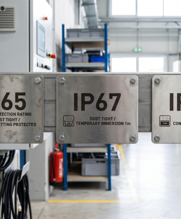
Humidity and condensation. Moisture ingress into the enclosure leads to internal corrosion, weak short circuits, and accelerated drift. This is where the importance of the IP rating (IP65, IP67, IP68) comes in – selected according to the actual exposure of the equipment.
5. Process-Related Problems
The process itself can corrupt the measurement without any sensor fault:
- Deposits on the sensing element – in electromagnetic flowmeters, ultrasonic level sensors, and pH probes. Deposits distort the measurement without triggering any alarm.
- Gas bubbles in liquid – significantly affect ultrasonic and vortex flowmeters, and under certain conditions, Coriolis meters as well.
- Unexpected changes in fluid properties – changes in density, viscosity, or conductivity can take the sensor’s calibration out of tolerance.
- Blockages in impulse lines – particles or condensate in the impulse line of a differential pressure transmitter can partially obstruct it. The sensor appears to function, but shows delayed or incorrect values.
6. Wiring and Signal Transmission Problems
A signal correctly generated by the sensor can arrive corrupted at the control system:
- Excessively long cables without adequate shielding
- Oxidised or loose connections
- Grounding at multiple points (ground loop)
- Excessive loop resistance on the 4-20 mA circuit, beyond the source capability
- Reversed polarity
- Signal cables routed parallel to power cables
With digital protocols (Modbus, HART, Profibus), incorrect bus termination or a mismatched baud rate can completely disrupt communication or introduce checksum errors.
7. Human and Operational Errors
The last category includes:
- Configuration settings changed without authorisation
- Incorrectly reprogrammed measurement ranges
- Incorrect units (bar vs PSI, °C vs °F)
- Damping/filter set to extreme values that mask real process variations
- Lack of training for personnel who interact with instruments
These errors are the hardest to detect because they leave no clear technical trace.
Specific Mistakes by Instrument Type
Pressure Transmitters
- Reversing impulse lines on DP transmitters (HP with LP)
- Incorrect impulse line slope (recommended ≥1/12, with different direction for liquid, gas, and steam)
- Impulse lines of different lengths – introduce temperature and density differences between the two legs
- Air pockets in liquid applications or condensate accumulation in gas applications
- Mechanically damaged diaphragm due to a pressure spike or corrosive medium
- Zero drift after installation due to the hydrostatic effect of the fluid column in the impulse line
Temperature Sensors (RTDs and Thermocouples)
- Insufficient immersion depth (less than 8–10 × thermowell diameter)
- Air gap between probe and thermowell bore – slow response, thermal error
- Thermocouple with reversed polarity – readings decrease when real temperature increases
- Extension cables of the wrong type for the thermocouple (extension cable type must match the thermocouple type – J, K, T, E, etc.)
- Thermocouple contamination by process medium (sulphur, phosphorus, lead rapidly degrade thermocouples)
- RTD: long cables on a 2-wire connection – error proportional to cable resistance; solution is 3-wire or 4-wire connection
- Damaged junction in thermocouple
Flowmeters
- Insufficient straight pipe run upstream and downstream
- Incompletely filled pipe (electromagnetic flowmeters, fixed-beam ultrasonics)
- Gas bubbles trapped in liquid (Coriolis, ultrasonic)
- Asymmetric flow profile due to partially open valves upstream
- Incorrect flow direction – flowmeter installed in reverse
- For meters with moving parts (turbine type) – undetected mechanical wear
Level Sensors
- Radar/ultrasonic level sensors affected by foam on the surface, steam, or condensate on the antenna
- Capacitive sensors affected by changes in the dielectric constant of the medium
- Hydrostatic sensors with zero drift due to changes in liquid density
- Complex tank geometry not accounted for during programming (sloped bottoms, cones, internal baffles)
How to Identify Incorrect Measurements
Measurement errors are not always obvious. The following signs should trigger an investigation:
- Mass balance discrepancies – inlet flow does not match outlet flow in a closed process (after accounting for hold-up).
- Stable but incorrect readings – the instrument appears “frozen” in a process that should be varying.
- Noisy readings without obvious cause – abnormal signal fluctuations in an otherwise stable process.
- Systematic drift over time – the baseline value changes progressively.
- Physically impossible readings – flow exceeding pump capacity, negative pressure where it should not exist.
- Discrepancy between redundant instruments – two transmitters on the same measurement point showing different values.
- Readings suspiciously close to zero, full scale, or a “round” value – instrument stuck or saturated.
The table below summarises the most common symptoms and their probable causes.
| Symptom | Probable Cause |
|---|---|
| Constant reading, no reaction to process | Blocked impulse line / sensor saturated / excessive damping |
| Reading changes in opposite direction | Reversed polarity / HP-LP lines swapped |
| Slow drift over time | Sensor aging / deposits / recalibration required |
| High signal noise | EMI / vibration / wiring problems |
| Slow response to changes | Insufficient immersion / condensate accumulation / excessive damping |
| Discrepancy with reference instrument | Calibration out of tolerance |
| Zero or over-range reading | Defective sensor / broken cable / configuration error |
Best Practices for Reducing Measurement Errors
Reducing measurement errors is not a one-time fix – it is a continuous process.
- Rigorous specification at the design stage. Define precisely: measurement range, required accuracy, environmental conditions, process medium properties, certifications (ATEX, IECEx, IP), communication protocol.
- Follow the manufacturer’s installation instructions. Straight pipe runs, immersion depths, impulse line slopes are not suggestions – they are the conditions under which the manufacturer verified the declared accuracy.
- Shielded and correctly grounded cables. Never routed parallel to power cables. Shield grounded at a single point only.
- Documented calibration plan. Regular verification at multiple points, using traceable instruments.
- Preventive maintenance. Periodic cleaning of sensing elements exposed to deposits. Regular inspection of enclosure integrity and cable connections.
- HART/IO-Link diagnostics. Modern sensors transmit additional information about their own health status – use it.
- Trained personnel. The best instrumentation is irrelevant if the people operating it do not understand it.
Three Practical Examples from the Field
Case 1 – Wastewater treatment plant, flowmeter on the effluent channel. The operator reported unrealistic flow variations. On inspection: the electromagnetic flowmeter was correctly calibrated, but had been installed 1 m upstream of a partially open valve. The asymmetric flow profile was introducing an error of approximately 8%. Solution: relocating the flowmeter with at least 10D distance from the valve, or replacing it with a model insensitive to flow profile disturbances.
Case 2 – Chemical reactor, unreliable temperature control. The Pt100 RTD was indicating temperatures 4–5°C below the real values verified with a reference instrument. Cause: the thermowell had been replaced with a thicker-walled variant, and the immersion depth was now below the required minimum. Thermal conduction through the flange was cooling the probe. Solution: fitting a thermowell adapted to the process geometry.
Case 3 – Steam line, DP transmitter with orifice plate for flow measurement. A systematic positive error of approximately 12%. Cause: one of the impulse lines was accumulating condensate due to incorrect slope. The difference in hydrostatic head between the two lines was being read as a real pressure difference. Solution: correcting the slope and installing equivalent condensate pots on both lines.
Conclusion
Incorrect measurements in industrial processes are almost never a sensor problem. They are the result of a combination of factors: wrong instrument selection, non-compliant installation, insufficient calibration, environmental conditions not accounted for, and absent maintenance.
The difference between a stable production line and a problematic one is, in many cases, the quality of instrumentation and the discipline with which it is maintained. The investment in correct specification, correct installation, and a rigorous calibration plan pays back quickly through reduced energy consumption, fewer rejects, and elimination of unplanned downtime.
For technical advice on selecting, sizing, and integrating the right industrial instrumentation for your process, the Divinov Engineering team provides specialised support – from pressure transmitters and flowmeters to complete measurement and control systems.